7 segment LED display | 0.4" inch | Smt package

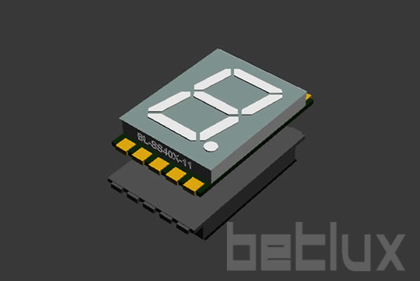
SMD seven segment display 0.4 inch

BL-SS40A-11,BL-SS40B-11

smd 7 segment LED display  | 0.47 segment LED display | 0.4" inch | Smt package
Brand BETLUX
Part NO BL-SS40A-11,BL-SS40B-11
Dimension 9.10*15.00*3.75 mm
Weight 0.7000g
Package 400pcs
Datasheet pdf
PrintEmail
Feature: Description

0.40 inch SMD single Numeric LED display
0.40 inch digit height(10.16mm)
widthxheight: 9.1X15mm
Single decimal point
Single LED chip per segment
Common anode or common cathode selected
Low Current Operation
Excellent Character Appearance
High Light Output
Easy Mounting On PC Boards
Multicolor Available
Categorized for Luminous Intensity
Technically Rugged
Standard: Gray Surface, White Segment
RoHs Compliance

RoHs Compliance, Pb-free Anti-Static Attention

Electrical-optical characteristics:

Part No C.C.Part No C.A.colorwavelengthV typical(V)V max(V)Brightness(mcd)
BL-SS40A-11S-XXBL-SS40B-11S-XXHigh Bright Red6601.852.28
BL-SS40A-11D-XXBL-SS40B-11D-XXSuper Bright Red6601.852.215
BL-SS40A-11UR-XXBL-SS40B-11UR-XXUltra Bright Red6601.852.217
BL-SS40A-11UHR-XXBL-SS40B-11UHR-XXUltra Breight Red6452.12.517
BL-SS40A-11E-XXBL-SS40B-11E-XXOrange6352.12.510
BL-SS40A-11UE-XXBL-SS40B-11UE-XXHigh Bright Orange6302.12.513
BL-SS40A-11YO-XXBL-SS40B-11YO-XXUltra Amber6192.12.513
BL-SS40A-11Y-XXBL-SS40B-11Y-XXYellow5852.12.510
BL-SS40A-11UY-XXBL-SS40B-11UY-XXHigh Bright Yellow5902.12.513
BL-SS40A-11G-XXBL-SS40B-11G-XXGreen5702.22.510
BL-SS40A-11UG-XXBL-SS40B-11UG-XXHigh Bright Green5742.22.515
BL-SS40A-11PG-XXBL-SS40B-11PG-XXSuper Pure Green5253.84.520
BL-SS40A-11B-XXBL-SS40B-11B-XXBlue4702.74.226
BL-SS40A-11W-XXBL-SS40B-11W-XXWhite-2.74.232


Package configuration & Internal circuit diagram
smd 7 segment LED display  | 0.4

All dimensions are in millimeters(inches)
Tolerance is +-0.25(0.01") unless otherwise note
Specifications are subject to change without notice.

Absolute maximum ratings (Ta= 25?C)

Reflector Surface color (1st number)/ Segment Lens color (2nd number):

Number 0 1 2 3 4 5
Ref Surface Color White Black Gray Red Green  
Epoxy Color Water clear White diffused Red Diffused Green Diffused Yellow Diffused  

Absolute maximum ratings (Ta= 25°C)

Parameter   S D UR E Y G Unit
Forward Current IF   25 25 25 25 25 30 mA
Power Dissipation Pd   60 60 60 60 60 65 mW
Reverse Voltage VR   5 5 5 5 5 5 V
Peak Forward Current IPF (Duty 1/10 @1KHZ)   150 150 150 150 150 150 mA
Operation Temperature TOPR -40 to +80 °C
Storage Temperature TSTG -40 to +85 °C
Lead Soldering Temperature TSOL   Max.260+ 5°C for 3 sec Max. ( 1.6mm from the base of the epoxy bulb) °C

Absolute maximum ratings (Ta= 25°C)

Parameter UHR UE YO UY UG PG UB UW Unit
Forward Current IF 30 30 30 30 30 30 30 30 mA
Power Dissipation Pd 75 65 65 65 75 110 120 120 mW
Reverse Voltage VR 5 5 5 5 5 5 5 5 V
Peak Forward Current IPF (Duty 1/10 @1KHZ) 150 150 150 150 150 150 100 100 mA
Operation Temperature TOPR -40 to +80 °C
Storage Temperature TSTG -40 to +85 °C
Lead Soldering Temperature TSOL Max.260+ 5°C for 3 sec Max. ( 1.6mm from the base of the epoxy bulb) °C

Partno description:

LED seven segment , called also LED numeric display, is widely applied in home appliance panel display and other application.

Part No of Seven segment LED display

Related Information

Applied for:
dvd player radio train instrument refrigerator

1. Application
The Seven Segment LED is widely applied for ordinary electronic equipment (such as office equipment,
communication equipment and household applications). Checking with BETLUX's Sales in
advance for information on applications in which exceptional reliability is required, particularly
when the failure or malfunction of the LEDs may directly jeopardize life or health (such as in
aviation, transportation, traffic control equipment, medical and life support systems and safety
devices).

2. Storage
The storage ambient for the Seven Segment LED should not exceed 30℃ temperature or 70% relative humidity.
For extended storage out of their original packaging, it is recommended that the Seven Segment LEDs be stored
in a sealed container with appropriate desiccant, or in a desiccator with nitrogen ambient.

3. Cleaning
Avoid using any unspecified chemical solvent to clean LED . For example, Trichloroethylene, Chlorosen, Acetone, and Diflon S3MC.
Any cleaning method can only be taken under normal temperature in one minute or less if it is required.
Use water to clean the Seven Segment LED if necessary under room temperature
dry it immediately after that.

4.Forming
Any unsuitable stress applied to the epoxy may break bonding wires in LED
Any forming on lead pin must be done before soldering, not during or after soldering.
Avoid applying any stress to resin in order to prevent the epoxy fracture and break on bonding wire.
While forming, please use a tie bar cut or equivalent to hold or bend the pin.
2mm from the base of resin is the minimum distance for the place bending the lead pin.
Avoid bending the lead pin at the same point twice or more.

seven segment display forming caution

Soldering

When soldering, leave a minimum of 2mm clearance from the base of the base of the lens to the soldering point. Dipping the lens into the solder must be avoided.

Do not apply any external stress to the lead frame during soldering while the LED is at high temperature.

Recommended soldering conditions:


IR Reflow Soldering (for SMD display) Wave Soldering Soldering Iron
Pre-Heat 150-180°C Pre-Heat 100°C Max. Temperature 300°C Max.
Pre-Heat Time 120sec Max. Pre-Heat Time 60sec Max.
Peak Temperature 260°C Max. SolderWave 260°C Max. Soldering Time 3sec Max.(one time only)
Soldering Time 10 sec Max. Soldering Time 5sec Max.

Note: Excessive soldering temperature and/or time might result in deformation of the LED lens or failure of the LED

ESD(Electrostatic Discharge)

Static Electricity or power surge will damage the LED.

Suggestions to prevent ESD (Electrostatic Discharge):

n Use a conductive wrist band or anti-electrostatic glove when handling these LEDs

n All devices, equipment, and machinery must be properly grounded

n Work tables, storage racks, etc. should be properly grounded

n Use ion blower to neutralize the static charge which might have built up on surface of the LED's

 plastic lens as a result of friction between LEDs during storage and handling

ESD-damaged LEDs will exhibit abnormal characteristics such as high reverse leakage current, 

low forward voltage, or “no light on” at low currents. To verify for ESD damage, check for “light on” 

and Vf of the suspect LEDs at low currents.

The Vf of “good” LEDs should be>2.0V@0.1mA for InGaN product and >1.4V@0.1mA for AlInGaP

 product.

antistatic notice-smd led


LED dirve IC by  Maxim Integrated

 MAX6959  4½-Digit LED Display Driver

 MAX6958  4½-Digit LED Display Driver

 MAX6955  7-, 14-, 16-Segment LED Display Driver

 MAX6956  LED Static Display Driver and I/O Port

 MAX6954  7-, 14-, 16-Segment LED Display Driver

 MAX6952  5 x 7 Matrix LED Display Driver

 MAX6957  LED Static Display Driver and I/O Port

MAX6950  5-Digit LED Display Driver

 MAX6951  8-Digit LED Display Driver

 ICM7212  4-Digit LED Driver

 ICM7212A  4-Digit LED Driver

 ICM7212AM  4-Digit LED Driver

 ICM7212M  4-Digit LED Driver

 ICM7218A  8-Digit LED Driver

 ICM7218B  8-Digit LED Driver

 ICM7218C  8-Digit LED Driver

 ICM7218D  8-Digit LED Driver

 MAX7221  8-Digit LED Display Driver

 MAX7219  8-Digit LED Display Driver

 provide in-depth design and IC selection help for design engineers.  Each solution is dedicated to a popular end-equipment type and features design information, circuits and a block diagram.   Within a block diagram, click on a block to view best-fit integrated circuits recommended by Maxim engineers.


Power source for digit display (5v/12v/24v AC/DC converter)

power supplierpower supplier

more information of LED power supplier