 5 watt LED | high power LED | LED products

 LED display and diode manufacturer,Betlux
LED digital world, share with you the quality LED technology
LED display and diode manufacturer,Betlux
LED digital world, share with you the quality LED technology
5 watt LED | high power LED | LED products
- You are here:
- Home

- LED diode
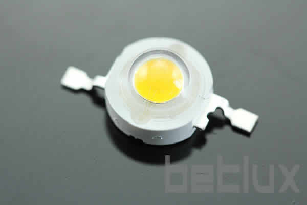
5W Emitter,HIGH POWER LED,Lamertian Type
BL-HP20EXXXL-5W
5 watt LED | high power LED | LED products
| Brand | BETLUX |
| Part NO | BL-HP20EXXXL-5W |
| Dimension | 20.00*20.00*5.10 mm |
| Weight | g |
| Package | |
| Datasheet |  |


Feature:
Description
Features:
1W and 3W, 5W LEDs suitable for illumination lamps and decorative lighting
Longer service and less luminosity loss, 50,000hours
Different emitting colors are available
Working current: 200-350mA, 700mA, 1050mA
With or without heat sink are
RoHs Compliance


Electrical-optical characteristics:
Package configuration & Internal circuit diagram
Tolerance is +-0.25(0.01") unless otherwise note
Specifications are subject to change without notice.
Absolute maximum ratings (Ta= 25?C)
Partno description:
High Power LED
Related Information
Applied for:


CAUTIONS for Power LED
Storage
n The storage ambient should not exceed 30℃ temperature or 70% relative humidity.
n For extended storage out of their original packaging, it is recommended that the LEDs be stored
in a sealed container with appropriate desiccant, or in a desiccator with nitrogen ambient.
n It is recommended that LEDs out of their original packaging are soldered within 4weeks.
n LEDs stored out of their original packaging for more than 4 weeks should be baked at about 60
deg C for at least 24 hours before solder assembly.
Assemble Consideration
This section provides you the requirements to mount BL-HP Emitters onto Metal Core Printed
Circuit Board (MCPCB)for optimal heat-dissipation efficiency, for reliable operations of your
products and for the optimal performance you need.
n Design rules during BL-HP Emitter array and its assembly procedure
1. Thermal resistance from the BL-HP Emitters to the ambient environment must be kept at minimum
level as possible. Any heat barrier will prevent BL-HP Emitters from running at optimum light output
performance.
2. Electrical insulation between the contacts other than electros of BL-HP Emitters and the MCPCB
is required. The exposed metal part of a BL-HP Emitters is not electrically neutral. Do not electrically
connect this area to any electrical traces or pads on your MCPCB.
3. If you want to minimize thermal resistance between BL-HP Emitters and your MCPCB, use
thermally conductive adhesive in-between.
4. BL-HP Emitter can be soldered in infrared (IR), hot bar soldering, fiber focused IR, or hand
soldering.
MCPCB Selection
To select a suitable MCPCB is the first step in assemble BLHP emitters. A MCPCB consists of
several layers that provide both electrical connections and a low thermal resistance path to external
heat sinks applied. Standard BLHP Emitter arrays use aluminates MCPCB that consists of the
following layers:
1.Aluminum Base ( thickness:1.5±0.1mm)
2. Electrical Insulation Layer (Dielectric/Epoxy thickness: 100µÌ)
3. Copper Layer (Copper thickness: 35µÌ
4. Solder Mask (Solder paste thickness after reflow process: 90~115µÌ
Thermal Consideration
n Thermal Resistance of BLHP Emitter
Thermal resistance (RTH) is one of the primary tools used in thermal management design. It is
defined as the ratio of temperature difference to the corresponding power dissipation. The overall
RTH,J-A (Junction-Ambient) of a BLHP Emitter plus MCPCB is illustrated as follow:
(1) RTH,J-A (℃/W) = △TJ-A / P d
Where
△ TJ-A = TJunction - TAmbient (℃)
Pd (Power dissipated, W) = Forward current (IF) × Forward voltage (VF)
In addition, heat generated at the junction of semiconductor die travels along the following path to
ambient environment: junction-to-board, board-to-ambient air.

Soldering Process
Followings are a recommend process flows to build BLHP Emitters into Power Light Sources.
Please mount entire respective surface mount devices (SMD), if any, on your MCPCB designated
before BLHP Emitters assembly process.
n For IR Reflow Soldering
Reflow soldering temperature profile

For Hot Bar
Step 1 Dispense Thermal Conductive Agent and Solder Flux
Use solder flux for good heat transfer during soldering of the BLHP Emitter terminals to reduce
required soldering time. Note that the spread of flux compound should be restricted to the solder pad
areas. You may want to optimize your soldering process by adjusting the amount of flux.
Step 2 Placement of BLHP Emitter
It is recommended to use automated pick-and-place equipment to place BLHP Emitters onto MCPCB.
The pick-and-place mechanism shall not touch the leads or the leads of BLHP Emitters.
Step 3 Soldering the Electrical Leads by Hot bar Soldering
This process will help transfer heat only on to the leads and solder pad areas and therefore avoid
damaging emitter body. To transfer sufficient heat from hot bars to device-leads, it is strongly
recommended that the following process parameters must be considered:
1)Amount of flux dispensed onto solder pads,
2) pressing force of hot bar tips, and
3)Hot bar temperature.
Step 4 Curing for Thermal Conductive Agent
Please follow the curing instructions set forth by manufacturers for the chosen thermal conductive
agent.
n For Manual Soldering Iron
When manual hand soldering is concerned, it is recommended to hand solder the leads with a
solder-tip temperature of 290℃ for less than 3 seconds and at least 2 seconds or more intervals
during each solder. Furthermore , avoid damaging the emitter or the epoxy layer on MCPCB
Static Electricity or power surge will damage the LED.
Suggestions to prevent ESD damage:
n Use a conductive wrist band or anti-electrostatic glove when handling these LEDs
n All devices, equipment, and machinery must be properly grounded
n Work tables, storage racks, etc. should be properly grounded
n Use ion blower to neutralize the static charge which might have built up on surface of the LED's
plastic lens as a result of friction between LEDs during storage and handling
ESD-damaged LEDs will exhibit abnormal characteristics such as high reverse leakage current,
low forward voltage, or “no light on” at low currents. To verify for ESD damage, check for “light on”
and Vf of the suspect LEDs at low currents.
The Vf of “good” LEDs should be>2.0V@0.1mA for InGaN product and >1.4V@0.1mA for AlInGaP
product.

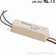
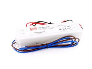
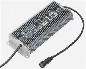
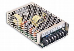
Power source for LEDs (5v/12v/24v AC/DC converter, DC/DC converter, waterproof/non-waterproof)
Related Products
 LED light bar (circle,20mm big LED)
Sales price:
|
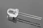 8mm LED diode
Sales price:
|
 3mm LED diode
Sales price:
|
 10mm LED diode
Sales price:
|
 4mm LED diode
Sales price:
|
 5mm LED diode
Sales price:
|
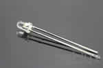
 1.8mm super bright LED diode
Sales price:
|
Related Categories
 SMD LED |
 power LED |
 Oval LED |
 IR LED |
 PHOTO DIODES |
 PIRANHA LED |
 BLINKING LED |
 MULTI-COLOR LED |
 LED bullet |
 SUPER BRIGHT LED |
SMD LED |
power LED |
Oval LED |
IR LED |
PHOTO DIODES |
PIRANHA LED |
BLINKING LED |
MULTI-COLOR LED |
LED bullet |
SUPER BRIGHT LED |