1. Application
The Dot Matrix display is widely applied for ordinary electronic equipment (such as office equipment,
communication equipment and household applications). Checking with BETLUX's Sales in
advance for information on applications in which exceptional reliability is required, particularly
when the failure or malfunction of the dot matrix LEDs may directly jeopardize life or health (such as in
aviation, transportation, traffic control equipment, medical and life support systems and safety
devices).
2. Storage
The storage ambient for the Seven Segment LED should not exceed 30℃ temperature or 70% relative humidity.
For extended storage out of their original packaging, it is recommended that the Seven Segment LEDs be stored
in a sealed container with appropriate desiccant, or in a desiccator with nitrogen ambient.
3. Cleaning
Avoid using any unspecified chemical solvent to clean LED . For example, Trichloroethylene, Chlorosen, Acetone, and Diflon S3MC.
Any cleaning method can only be taken under normal temperature in one minute or less if it is required.
Use water to clean the Dot MatrixLED if necessary under room temperature
dry it immediately after that.
4.Forming
Any unsuitable stress applied to the epoxy may break bonding wires in Dot matrix LED
Any forming on lead pin must be done before soldering, not during or after soldering.
Avoid applying any stress to resin in order to prevent the epoxy fracture and break on bonding wire.
While forming, please use a tie bar cut or equivalent to hold or bend the pin.
2mm from the base of resin is the minimum distance for the place bending the lead pin.
Avoid bending the lead pin at the same point twice or more.
Soldering
When soldering, leave a minimum of 2mm clearance from the base of the base of the lens to the soldering point. Dipping the lens into the solder must be avoided.
Do not apply any external stress to the lead frame during soldering while the LED is at high temperature.
Recommended soldering conditions:
| Wave Soldering |
Soldering Iron |
| Pre-Heat |
100°C Max. |
Temperature |
300°C Max. |
| Pre-Heat Time |
60sec Max. |
| SolderWave |
260°C Max. |
Soldering Time |
3sec Max.(one time only) |
| Soldering Time |
5sec Max. |
Note: Excessive soldering temperature and/or time might result in deformation of the LED lens or failure of the LED
ESD (Electrostatic Discharge)
Static Electricity or power surge will damage the LED.
Suggestions to prevent ESD damage:
n Use a conductive wrist band or anti-electrostatic glove when handling these LEDs
n All devices, equipment, and machinery must be properly grounded
n Work tables, storage racks, etc. should be properly grounded
n Use ion blower to neutralize the static charge which might have built up on surface of the LED's
plastic lens as a result of friction between LEDs during storage and handling
ESD-damaged LEDs will exhibit abnormal characteristics such as high reverse leakage current,
low forward voltage, or “no light on” at low currents. To verify for ESD damage, check for “light on”
and Vf of the suspect LEDs at low currents.
The Vf of “good” LEDs should be>2.0V@0.1mA for InGaN product and >1.4V@0.1mA for AlInGaP
product.

LED dirve IC by Maxim Integrated
MAX6979 16-Port, 5.5V LED Driver with LED Fault Detection and Watchdog
MAX6971 16-Port, 36V LED Driver
MAX6962 4-Wire Serially Interfaced 8 x 8 Matrix Graphic LED Drivers
MAX6963 4-Wire Serially Interfaced 8 x 8 Matrix Graphic LED Drivers
MAX6960 8x8 Graphic Matrix LED driver
MAX6961 4-Wire Serially Interfaced 8 x 8 Matrix Graphic LED Drivers
MAX6969 16-Port, 5.5V LED Driver
MAX6978 8-Port, 5.5V LED Driver with Fault Detection and Watchdog
MAX6977 8-Port, 5.5V LED Driver with Fault Detection
MAX6968 8-Port, 5.5V LED Driver
MAX6967 LED Driver with PWM Intensity Control
MAX6966 LED Driver with PWM Intensity Control
MAX6964 LED Driver with PWM Intensity Control
MAX6965 LED Driver with PWM Intensity Control
MAX6953 5 x 7 Matrix LED Display Driver
provide in-depth design and IC selection help for design engineers. Each solution is dedicated to a popular end-equipment type and features design information, circuits and a block diagram. Within a block diagram, click on a block to view best-fit integrated circuits recommended by Maxim engineers.
 8x8 led bicolor circuit

 LED display and diode manufacturer,Betlux
LED digital world, share with you the quality LED technology
LED display and diode manufacturer,Betlux
LED digital world, share with you the quality LED technology


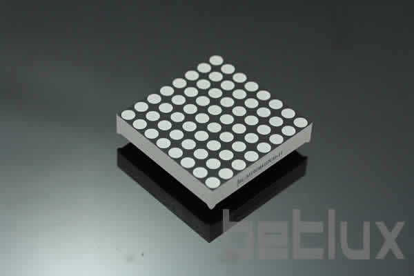
 5x7 dot matrix
  5x8 dot matrix
  5x9 dot matrix
  6x7 dot matrix
  8x8 dot matrix