dot matrix LED | 2.54mm dot | 5x7 matrix

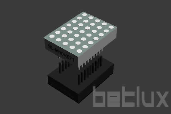
dot matrix LED 2.54mm 5x7

BL-M10A571,BL-M10B571

dot matrix LED | 2.54mm dot | 5x7 matrixdot matrix LED | 2.54mm dot | 5x7 matrix
Brand BETLUX
Part NO BL-M10A571,BL-M10B571
Dimension 19.96*27.94*6.35 mm
Weight 6.3000g
Package 64pcs/bag
Datasheet pdf
PrintEmail
Feature: Description

1.0 inch height 5x7 LED dot matrix
1.0 inch Matrix Height(26.54mm)
Dot size 2.54mm, circle dot
Column: 5 Row: 7
Widthxheight: 19.96x27.94mm
Low current operation
High contrast and light output
Compatible with ASCII and EBCDIC code
Stackable horizontally
Column cathode and column anode available
Easy mounting on P.C.Boards or Sockets
Categorized for luminous intensity
Technically rugged
Standard: Gary surface and White dot

RoHs Compliance, Pb-free Anti-Static Attention

Electrical-optical characteristics:

Row CathodePart No (row anode, column cathode)colorwavelengthV typical(V)V max(V)Brightness(mcd)
BL-M10A571SBL-M10B571SHigh Bright Red6601.852.2100
BL-M10A571DBL-M10B571DSuper Bright Red6601.852.2110
BL-M10A571URBL-M10B571URUltra Bright Red6601.852.2120
BL-M10A571UHRBL-M10B571UHRUltra Breight Red6452.12.5120
BL-M10A571EBL-M10B571EOrange6352.12.590
BL-M10A571UEBL-M10B571UEHigh Bright Orange6302.12.5100
BL-M10A571YOBL-M10B571YOUltra Amber6192.12.5100
BL-M10A571YBL-M10B571YYellow5852.12.590
BL-M10A571UYBL-M10B571UYHigh Bright Yellow5902.12.5100
BL-M10A571GBL-M10B571GGreen5702.22.595
BL-M10A571UGBL-M10B571UGHigh Bright Green5742.22.5130
BL-M10A571PGBL-M10B571PGSuper Pure Green5253.84.5150
BL-M10A571BBL-M10B571BBlue4702.74.270
BL-M10A571WBL-M10B571WWhite-2.74.2100


Package configuration & Internal circuit diagram
dot matrix LED | 2.54mm dot | 5x7 matrix dimensional drawing

All dimensions are in millimeters(inches)
Tolerance is +-0.25(0.01") unless otherwise note
Specifications are subject to change without notice.

Absolute maximum ratings (Ta= 25?C)

Reflector Surface color (1st number)/ dot Lens color (2nd number):

Number 0 1 2 3 4 5
Ref Surface Color White Black Gray Red Green  
Dot Epoxy Color Water clear White diffused Red Diffused Green Diffused Yellow Diffused  

Absolute maximum ratings (Ta= 25°C)

Parameter   S D UR E Y G Unit
Forward Current IF   25 25 25 25 25 30 mA
Power Dissipation Pd   60 60 60 60 60 65 mW
Reverse Voltage VR   5 5 5 5 5 5 V
Peak Forward Current IPF (Duty 1/10 @1KHZ)   150 150 150 150 150 150 mA
Operation Temperature TOPR -40 to +80 °C
Storage Temperature TSTG -40 to +85 °C
Lead Soldering Temperature TSOL   Max.260+ 5°C for 3 sec Max. ( 1.6mm from the base of the epoxy bulb) °C

Absolute maximum ratings (Ta= 25°C)

Parameter UHR UE YO UY UG PG UB UW Unit
Forward Current IF 30 30 30 30 30 30 30 30 mA
Power Dissipation Pd 75 65 65 65 75 110 120 120 mW
Reverse Voltage VR 5 5 5 5 5 5 5 5 V
Peak Forward Current IPF (Duty 1/10 @1KHZ) 150 150 150 150 150 150 100 100 mA
Operation Temperature TOPR -40 to +80 °C
Storage Temperature TSTG -40 to +85 °C
Lead Soldering Temperature TSOL Max.260+ 5°C for 3 sec Max. ( 1.6mm from the base of the epoxy bulb) °C

Partno description:

LED dot matrix is widely used in LED information board indoor and semi-outdoor

Part No of LED dot matrix

Related Information

Applied for:
trainbus information boardLED screnmessage boardindustry instrument

1. Application
The Dot Matrix display is widely applied for ordinary electronic equipment (such as office equipment,
communication equipment and household applications). Checking with BETLUX's Sales in
advance for information on applications in which exceptional reliability is required, particularly
when the failure or malfunction of the dot matrix LEDs may directly jeopardize life or health (such as in
aviation, transportation, traffic control equipment, medical and life support systems and safety
devices).

2. Storage
The storage ambient for the Seven Segment LED should not exceed 30℃ temperature or 70% relative humidity.
For extended storage out of their original packaging, it is recommended that the Seven Segment LEDs be stored
in a sealed container with appropriate desiccant, or in a desiccator with nitrogen ambient.

3. Cleaning
Avoid using any unspecified chemical solvent to clean LED . For example, Trichloroethylene, Chlorosen, Acetone, and Diflon S3MC.
Any cleaning method can only be taken under normal temperature in one minute or less if it is required.
Use water to clean the Dot MatrixLED if necessary under room temperature
dry it immediately after that.

4.Forming
Any unsuitable stress applied to the epoxy may break bonding wires in Dot matrix LED
Any forming on lead pin must be done before soldering, not during or after soldering.
Avoid applying any stress to resin in order to prevent the epoxy fracture and break on bonding wire.
While forming, please use a tie bar cut or equivalent to hold or bend the pin.
2mm from the base of resin is the minimum distance for the place bending the lead pin.
Avoid bending the lead pin at the same point twice or more.

seven segment display forming caution

Soldering

When soldering, leave a minimum of 2mm clearance from the base of the base of the lens to the soldering point. Dipping the lens into the solder must be avoided.

Do not apply any external stress to the lead frame during soldering while the LED is at high temperature.

Recommended soldering conditions:

Wave Soldering Soldering Iron
Pre-Heat 100°C Max. Temperature 300°C Max.
Pre-Heat Time 60sec Max.
SolderWave 260°C Max. Soldering Time 3sec Max.(one time only)
Soldering Time 5sec Max.

Note: Excessive soldering temperature and/or time might result in deformation of the LED lens or failure of the LED

ESD (Electrostatic Discharge)

Static Electricity or power surge will damage the LED.

Suggestions to prevent ESD damage:

n Use a conductive wrist band or anti-electrostatic glove when handling these LEDs

n All devices, equipment, and machinery must be properly grounded

n Work tables, storage racks, etc. should be properly grounded

n Use ion blower to neutralize the static charge which might have built up on surface of the LED's

 plastic lens as a result of friction between LEDs during storage and handling

ESD-damaged LEDs will exhibit abnormal characteristics such as high reverse leakage current, 

low forward voltage, or “no light on” at low currents. To verify for ESD damage, check for “light on” 

and Vf of the suspect LEDs at low currents.

The Vf of “good” LEDs should be>2.0V@0.1mA for InGaN product and >1.4V@0.1mA for AlInGaP

 product.

antistatic notice-smd led

LED dirve IC by  Maxim Integrated


 MAX6979  16-Port, 5.5V LED Driver with LED Fault Detection and Watchdog

 MAX6971  16-Port, 36V LED Driver

 MAX6962  4-Wire Serially Interfaced 8 x 8 Matrix Graphic LED Drivers

 MAX6963  4-Wire Serially Interfaced 8 x 8 Matrix Graphic LED Drivers

 MAX6960  8x8 Graphic Matrix LED driver

 MAX6961  4-Wire Serially Interfaced 8 x 8 Matrix Graphic LED Drivers

 MAX6969  16-Port, 5.5V LED Driver

 MAX6978  8-Port, 5.5V LED Driver with Fault Detection and Watchdog

 MAX6977  8-Port, 5.5V LED Driver with Fault Detection

 MAX6968  8-Port, 5.5V LED Driver

 MAX6967  LED Driver with PWM Intensity Control

 MAX6966  LED Driver with PWM Intensity Control

 MAX6964  LED Driver with PWM Intensity Control

 MAX6965  LED Driver with PWM Intensity Control

 MAX6953  5 x 7 Matrix LED Display Driver

 provide in-depth design and IC selection help for design engineers.  Each solution is dedicated to a popular end-equipment type and features design information, circuits and a block diagram.   Within a block diagram, click on a block to view best-fit integrated circuits recommended by Maxim engineers.


Power source for digit display (5v/12v/24v AC/DC converter)

power supplierpower supplier

more information of LED power supplier